Solar Project: The Wilson House
|
tkjhlkj |
The In-Floor
Radiant Heating System |
|||||||||||||||||||||||||||||||||||||||||||||||||||||||||||||||||||||||||||||||||||||||||||||||||||||||||||||||||||||||||||||||||||||||||||||||||||||||||||||||||||||||||||||||||||||||||||||||||||||||||||
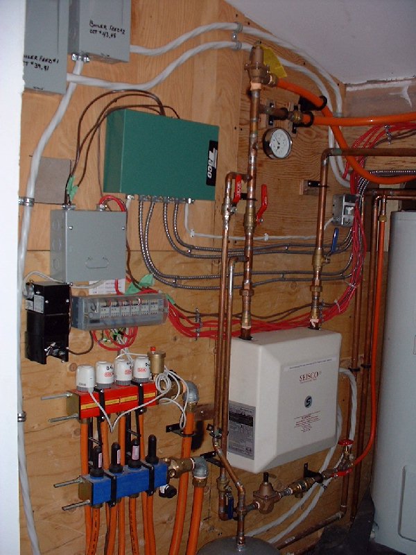
| December 2, 2001 - The square white unit with the Seisco label is the main "furnace" for the entire house. This ultra-efficient water heating device uses electricity to heat water on demand to be supplied to zones in the house. Each zone in the house has it's own thermostatic control. The Seisco Microtherm device requires to electrical fees as shown in the upper left. The green Taco device provides a relay control system for the valves for the piping into the floor. This controller is initiatted by the smaller controler below which gets all of the signals through the red wiring from each thermostat. The in-floor tubing in this picture are only for the 2nd floor rooms. The others are on the wall to the left (not visible in this picture). | |||||||||||||||||||||||||||||||||||||||||||||||||||||||||||||||||||||||||||||||||||||||||||||||||||||||||||||||||||||||||||||||||||||||||||||||||||||||||||||||||||||||||||||||||||||||||||||||||||||||||||||
 |
|||||||||||||||||||||||||||||||||||||||||||||||||||||||||||||||||||||||||||||||||||||||||||||||||||||||||||||||||||||||||||||||||||||||||||||||||||||||||||||||||||||||||||||||||||||||||||||||||||||||||||||
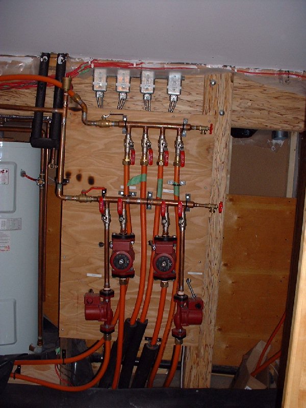
| December 2, 2001 - The flow of heated water into the tubing is provided by pumps for each zone. Each pump has a main shut off switch at the top of the picture. To the left side, with the black foam pipe insulation, is the future in-take for the solar water heater which will be mounted on the roof on the south face. The solar water heater will minimize the electrical energy required to heat the water. On the far left in the backgroun is an electric hot water tank used for the bath, shower and sinks. This system is separated from the in-floor water heating system. | |||||||||||||||||||||||||||||||||||||||||||||||||||||||||||||||||||||||||||||||||||||||||||||||||||||||||||||||||||||||||||||||||||||||||||||||||||||||||||||||||||||||||||||||||||||||||||||||||||||||||||||
 |
|||||||||||||||||||||||||||||||||||||||||||||||||||||||||||||||||||||||||||||||||||||||||||||||||||||||||||||||||||||||||||||||||||||||||||||||||||||||||||||||||||||||||||||||||||||||||||||||||||||||||||||
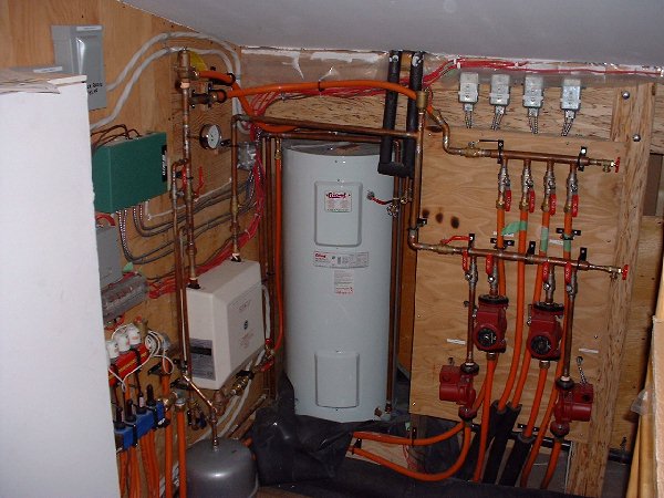
| December 2, 2001 - The utility room for the entire homes heating system is located on the 2nd floor north of the bathroom. This picture shows the entire mechanical room. | |||||||||||||||||||||||||||||||||||||||||||||||||||||||||||||||||||||||||||||||||||||||||||||||||||||||||||||||||||||||||||||||||||||||||||||||||||||||||||||||||||||||||||||||||||||||||||||||||||||||||||||
 |
|||||||||||||||||||||||||||||||||||||||||||||||||||||||||||||||||||||||||||||||||||||||||||||||||||||||||||||||||||||||||||||||||||||||||||||||||||||||||||||||||||||||||||||||||||||||||||||||||||||||||||||
| Copyright 2001 John Wilson | |||||||||||||||||||||||||||||||||||||||||||||||||||||||||||||||||||||||||||||||||||||||||||||||||||||||||||||||||||||||||||||||||||||||||||||||||||||||||||||||||||||||||||||||||||||||||||||||||||||||||||||